I was so jazzed with the concept that I built one that had as I recall 7 bands of audio separation. I had to use precision capacitors and resistors to make the filters, and I had to optimize the gain in each channel, and I mixed each channel on alternating inputs on a differential amp to cancel out crud. It worked amazing well. I could obtain 20dB of clipping with very little in the way of objectionable audio. It took a lot of work to optimize AND all those op amps were very particular about ANY RF getting into their little brains. I was running considerable power in those days, and it took me as long to get the RF out as it did to build the entire thing. I spent months on the design part procurement construction, tuning, testing and de-RFing. But I had a total blast building it, and I used it for years after. It had smooth audio and plenty of punch as long as there was NO common mode RF circling my shack
Today I received from Eric KE5DTO, the VP of software engineering at Flex an email that looks at how he designed the compander in the F5K. His compander has better audio than my brainstorm, and beats the pants off the Vomax entirely.
From Eric:
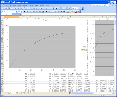
You can think of the compander as a black box that takes a waveform (audio samples) into the front end, applies some magic formula to those samples, and then spits it out on the other end for the output. The magic part is what is interesting. If you map the input to the output on an x-y plot with the compander off, it would look like a flat line (see compandoff). When it is on, the input samples are mapped in a way that increases the average power (see compand3) which shows what CPDR set to 3 looks like). The DX button is simply a VERY strong version of the compander (see DXcompand3 ) which shows what DX set to 3 looks like.
I'm also attaching the spreadsheet that I used to model the compander using Phil Harman's excel method. Playing with the values on the left, you can see how it affects a sine wave input, the input/output mapping, and the power/voltage increase due to the transformation.
Note that the value to play with is called fac (for factor). This value is -0.3 * the value of the slider for the compander (e.g. -0.9 for a value of 3, as described above and shown in wscompand2.png). For DX, this is -1.0 - 0.3 * the value of the DX slider (or -2.2 as shown in DXcompand3).
Compand set to Off (compandoff)

Compand set to 3 (compand3)

DXcompand set to 3 (DXcompand3)

So here it is, and here is how easy it is to model and produce a product that beats the pants off what I toiled over for months 30 years ago.
Here is a link to the spread sheet if you want to play with that:
Compander in a spreadsheet
To change the sheet adjust the value of "fac" in the sheet
This is a wonderful example of how SDR is such a different model, and a different way of thinking compared to the the analogue world. My circuit based compressor was basically fixed in stone. If I wanted to change anything it would have meant rebuilding the ENTIRE circuit, and then going through the painstaking normalization of each filter. No way Jose. Here you just screw around with something called "fac" and possibly a few other values in a spread sheet to determine how aggressive you want your audio to be compressed.
I got one word for you my boy: PLASTICS
and Paul Simon sings: "coo coo ca choo Mrs. Robin..."
73
Update:
I had a recent email, and came to find out it was Frank AB2KT who wrote the code for the compander. The letter I got from Eric was in response to my asking the question: "how does the compander work?", and I just assumed Eric was the author...my bad
As the history of this gets written I think it is important to try accurately chronicle the development since there has been a ton of collaboration by authors in this endeavor, and a ton of really fantastic intellectual property created, and Frank has done a lot of the creation. That to a large extent is what draws me to this radio. The way things come together and ideas that becomes a real tangible thing I can use every morning while I am spelunking the grey line. This idea was published in a Music Journal. I've read a lot of journals but I never read a Music Journal, and I find it fascinating from where the idea came into existence. To me its as fascinating as the fact that the MRI came from a device that was made to measure spin states in molecules in a chemistry lab. In fact if we had left the notion of "curing Polio" to the engineers we would have wound up with very compact efficient Iron lung as the solution, not the brainstorm of some Virologist. Very Cool.
In part here is what Frank had to say:
"I wrote it, based on a series of articles on nonlinear waveshaping that originally appeared in the AES Journal and Computer Music Journal back in the early 70's, developed by Arfib and Manes."
Amazing!!
This means while I was soldering together my brainstorm split band processor (an engineering solution) in the 70's, the idea for the flex compander was being created as well, published in a Music Journal, and Frank brought that knowledge into reality. Good stuff!!! Probably no one else in the universe see the beauty in that, but then that's why I'm here :)
Are roofing filters just another example of really small Iron lungs?
73
